
I Need Photos of BOD
Home › Forums › General Olson 30 Discussions › I Need Photos of BOD
This topic contains 26 replies, has 11 voices, and was last updated by 
-
AuthorPosts
-
January 22, 2012 at 5:17 am #1866
Can anyone email me photos of their Beams Of Destiny. The carbon fiber ones are too expensive and I hear they were having quality control problems — ( thus no longer available ). I want to fabricate my own and I am looking for different ideas. THANKS cnizett@hotmail.com
January 22, 2012 at 2:03 pm #2550I don’t have one, but your question begs the question of “why?” do we need one? I feel that maybe the frame (wishful thinking) I replaced below the mast will solve the compression problems of the O30. I have an attachment on the front of the mast to the deck (below deck) that prevents the deck rising. If the deck can’t rise, how would a bod help?
Looking for reasons….sorry about the hijack of your topic..but it seems the right thing to discuss before you ‘engineer’ a new one.
January 22, 2012 at 6:14 pm #2552I’ll see if I can get some beam photo’s for you today.
I’ll also post the photo’s of our cut away cabin top ;(
Love that rotted balsaJanuary 22, 2012 at 7:28 pm #2553Pics from 4 different boats are posted at: http://www.olsonuldb.com/olson30/tips/BOD-JS.html
The only real advantage to the carbon beam is that because it is arched it is much easier to get to the forepeak, which is not a inconsequential factor. My boat has the Pride Marine carbon beam which is very slick, though it came with it. I probably would have gone with a cheeper solution if I were doing it myself. A straight bar is much cheeper and probably stiffer than the carbon beams. Al Holt on “Kestrel” has a very simple and bullet proof solution. Ask him for pics. If I recall it’s a piece of angle iron tied into the chain plates and pinned to the mast. I am sure he can provide details.
January 22, 2012 at 8:15 pm #2554Here’s a picture of mine on Kestrel. It is 1/5″x1/5″x3/16″ aluminum alloy 6061 that I bought from McMaster Carr online. I needed slightly longer bolts at the ends for going through the chainplates. It’s a pretty inexpensive fix. You can see that it is fastened at the mast. I tried it first without pinning it at the mast and it buckled when I tightened the shrouds. I haven’t had any problem since pinning it at the halfway point. The reason for using the BOD is to help keep the boat from flexing. When a gust hits and you have 6 heavies on the rail, any flexing of the boat changes the sail shape in the wrong direction. A STIFF BOAT IS A HAPPY BOAT.
January 22, 2012 at 8:26 pm #2555I have a turnbuckle attached to the front side of the mast that goes up to the deck. Was this ‘standard’?
To me…if the deck can’t go up, the chainplates don’t come in.
Al..your .docx file won’t work. Change it to a jpeg?
January 22, 2012 at 8:40 pm #2556My JPEG was too big so I tried DOCX as a workaround. I don’t know how to compress the file. Re: turnbuckle. All three of the Olson 30s I have owned have the turnbuckle. Yes, it might be a tiny help, but trust me, it makes very little difference in preventing the hull from compressing. I replaced the turnbuckle with a solid piece of aluminum precisly cut to length. It prevents the deck from moving either way, up or down. This is needed because of big guys walking on the deck and large forces from halyards pulling the deck up. Please note: That aluminum angle buckled when I tightened the shrouds without pinning the angle at the halfway point. That’s a solid experimental result. Yes the deck was pinned to the mast at the partners. Can anybody help me with compressing these files? I’ll email them to you and you can post them…or whatever. al@holtmarinesystems.com
January 22, 2012 at 9:05 pm #2557Okay. Here’s the picture of Kestrel’s BOD.
January 22, 2012 at 9:06 pm #2558Bruce,
Your theory is correct but flawed. The purpose of the BOD is to keep the hull from shrugging by acting as a spreader. Yes if you hold the deck down it will attempt to keep the hull from shrugging but its not very stiff. Think of the BOD as a spreader and the jock straps as shrouds all below the deck. By using these you isolate the stresses from the hull. The only weak point in the system is the sheer load on the chain plate bolts which tend to pass through the bulkhead at an angle. What helps here is a backing plate on the front side of the bulkhead opposing the chainplates. I used G-10 material.
Ballanger sels a real nice jock strap setup that looks as good as it is functional. The BOD can be something as elaborate as the curved spreader like I have from David Wilby, expensive but effective. It can also be as simple as a piece of 2″ aluminum angle. With that you lose a lot of headroom making it difficult to access the forepeak area if your a larger person.
In conclusion, using the BOD / jock strap system you greatly reduce the stress on the hull and bulkheads and it allows you to get more tension on your shrouds since the whole rig becomes stiffer. Without this as you tension your rig it has a spongy behavior and everything is flexing.January 23, 2012 at 4:09 am #2560Thanks you guys. All this info is GREAT. Any other photos or other ideas for the BOD will be greatly appreciated.
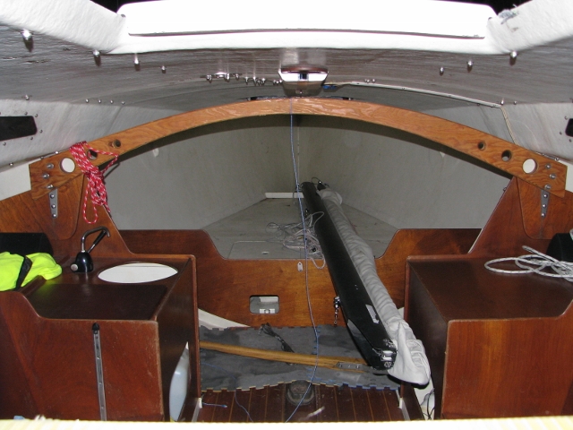
January 23, 2012 at 8:41 pm #2565Here is mine. It is vertically laminated ply….forget what wood it is. Pretty easy to make, even with the curve. We lash the middle to the mast. It definitely does stiffen up the boat! Notice the lightning holes…gucci!
 January 23, 2012 at 8:59 pm #2566
Hey Scott, that’s snazzy. Do you have a separate assembly on each side of the chainplate bulkhead or just the one BOD fastened to aft side…the one we can see?
January 23, 2012 at 9:00 pm #2567Old School..want to sell your stove tracks?
January 23, 2012 at 9:02 pm #2568Or is Dari selling some off his boat? Mine were missing when I bought the boat. We have to have cooking for the Chicago Mac race. I have the stove.
January 23, 2012 at 9:48 pm #2572# Al…no, the attachment is only on the aft side, as you see. The beam is about 2 inches thick.
#Bruce…not planning on selling them…much for the same reason you want them! What did you do on previous mac’s?
January 24, 2012 at 2:53 am #2574Hey Old School, That looks like a set up that will work well and I can build it myself. THANKS. Do you use jock straps? It does’nt look like your mast plate is set up for them.
January 24, 2012 at 4:06 am #2575No jockstraps. I am considering adding a version of straps this spring, even though I am not completely convinced they are required.
January 24, 2012 at 4:54 am #2576I didn’t get photos, sorry. Fast Company’s beam follows the cabin top w/ about a 1″ gap above and is laminated 1/4″ marine ply X 5. We also have it held down in the center w/ “amsteel” to mast step. The shape gives good head room and the amsteel prevents any upward bend. I thing the jock straps help a lot. We like our rig very stiff and this setup allows this w/o hull deformation.
January 24, 2012 at 5:23 am #2577Hey Scott and Jim, are your wood based beams glassed as all or just straight plywood? I am wondering if a glass and resin covered marine plywood bean wouldn’t be an even better solution, still easily homebuilt?
As for the jockstraps, I have tinkered with my rig endlessly and have found that there is a very direct connection between the tension in the straps and the loads in the shrouds. Which means there is deformation in the hull without the straps when the shrouds are loaded. This can be seen just sitting at the dock and tinkering. However, I also found when I really pushed the boat in a blow with the straps loose and 6 on the rail, it was essentially impossible to keep the mast from falling off [i.e the lee shrouds would be noodleing and sail shape suffering]. I view the BOD as a spreader and the straps as a continuation of the shrouds to the mast step. This is all the more relevant in systems where the beam is pinned to the mast. Thus the loads are contained to a closed system leaving the somewhat flexible hull and deck out of the equation [relatively speaking]. Scott may be correct that they are not necessary, but when the wind picks up on a W/L course with a crew loading the boat up I think that it really helps. Then again Scott seems to sail pretty fast without them…
January 24, 2012 at 5:36 am #2578Or even better you could take layers of say quarter inch ply, cut them to a templet, and laminate them together with resin and a layer of glass between them. Trim the excess and sand. There would be no need to wrap the outside or try to make it look pretty as the outside layers would still be just wood. That would be very easy to make and extremely strong in compression, tension and torsion.
January 24, 2012 at 6:47 am #2579Jonathan,
Hind sight I would have added fiberglass to the laminate or carbon fiber.
Again if I remember I’ll get photo’s of ours.January 24, 2012 at 11:14 am #2580Here is what I did with aluminum tube, cost $60 I think and minimal time
http://www.olson30.org/groups/friends/forum/topic/beam-of-destinyjockstraps-installed/January 24, 2012 at 11:53 am #2581Ours is simply marine ply with good marine-grade glue, many clamps.
January 24, 2012 at 4:07 pm #2582I used John Churchill post last summer took diagram to local steel shop. Schedule 20 alluminum Under 60.00 for me also fits well, Works well, New beam and old beam pictures shown.
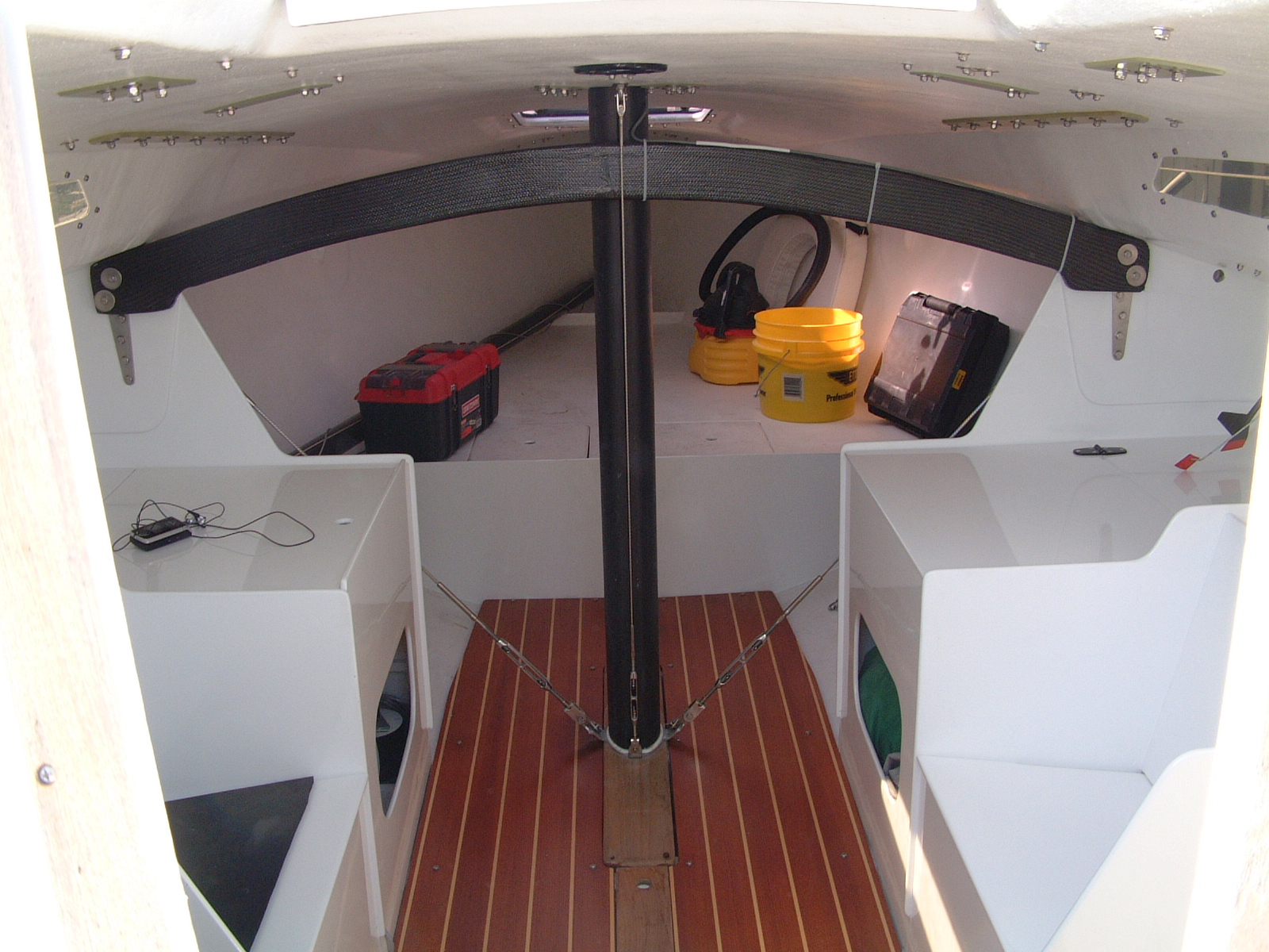
January 30, 2012 at 3:32 am #2600This one is made with sitka spruce and glassed
January 30, 2012 at 3:33 am #2601Mast base set up, pad is adjustable fore and aft.
January 23, 2015 at 8:04 pm #3654to andrew bish –
in this photo:
http://www.olson30.org/wp-content/uploads/ubpfattach/picture-035.jpg
what is the thickness of the G10/FR4 sheet used? are all the backing plates the same thickness?
-
AuthorPosts


You must be logged in to reply to this topic.